|
Introduction
Keeping pace with rapid changes in technology
can be both difficult and frustrating. This is especially true when creating
and maintaining map data within a digital environment. As the evolutionary
path of data creation and updating has moved toward greater use of digital
image products, analog aerial photographs have had to be scanned and rectified
in order to efficiently transfer critical data into GIS systems.
 This process has been, and remains, one that is necessary to make the
interpreted data more useful. Methods and techniques that decrease the
time it takes to transfer photo details reduce the cost of labor for map
production. As forest mapping has evolved from an analog to a digital
process, methods to obtain details from interpreted photographs have also
changed. With these changes have come greater complexity and the need
for increased knowledge in image scanning, rectification, and image-processing
techniques. While some types of digital imagery are used for interpretation,
the immense informational content of conventional aerial photographs will
secure their place in forest mapping for years to come. Having good stereoviewing
capability allows users to see and extract maximum feature content of
the imagery. The difficulty in using an analog product in an increasingly
digital world has led to the development of a new instrument to digitally
compile details directly from photos without the need for scanning.
This process has been, and remains, one that is necessary to make the
interpreted data more useful. Methods and techniques that decrease the
time it takes to transfer photo details reduce the cost of labor for map
production. As forest mapping has evolved from an analog to a digital
process, methods to obtain details from interpreted photographs have also
changed. With these changes have come greater complexity and the need
for increased knowledge in image scanning, rectification, and image-processing
techniques. While some types of digital imagery are used for interpretation,
the immense informational content of conventional aerial photographs will
secure their place in forest mapping for years to come. Having good stereoviewing
capability allows users to see and extract maximum feature content of
the imagery. The difficulty in using an analog product in an increasingly
digital world has led to the development of a new instrument to digitally
compile details directly from photos without the need for scanning.
Traditional Methods
Generally, stand detail transfer is made from a single photographic print
or transparency, since the use of more expensive stereoplotting equipment
has historically been cost-prohibitive. Traditional methods used to place
interpreted features in their correct position on a map have relied upon
a planimetrically controlled base. This base could either be constructed
by standard photogrammetric processes, or by using available maps such
as those supplied by the U.S. Geological Survey. Base map scale must closely
approximate photographic scale, or else the distortion inherent in a single
photograph is increased when enlarging a small-scale photo to fit a large-scale
base map.
Among the several types of single-photo
instruments that use the camera lucida principle, probably the most familiar
to foresters are the vertical sketchmaster and the Bausch and Lomb Zoom
Transfer Scope. Other such products include reflecting projectors, mirror
stereoscopes with plotting arms, and several types of stereo pantographs
that are designed to allow scale adjustments of greater magnitude between
the photograph and the base map. Confining delineated features to the
area of least distortion of each photo (effective area) allowed reasonable
adjustments to compensate for slight scale changes, tip or tilt elements,
and some relief displacement present on each photograph. The Zoom Transfer
Scope allows optical adjustments within the viewing area to help "fit"
the photo features to their correct locations by combining scale, stretch
and rotation to the viewed image as it is overlaid on the base.
Digital Image Methods
If aerial photo images are to be adjusted to fit a particular map projection
as represented by a digital data set, the images must either be georeferenced,
rectified, or converted into ortho-images. The choice of which process
to use depends upon the accuracy of the base data, the compilation scale,
and the final accuracy level desired. In any case, if image data is to
be adjusted in digital form it must also exist in digital form, whether
scanned or digitally acquired.
With the exception of using imagery that
is digitally acquired, the "digital solution" to using conventional aerial
photographs for forest mapping is to scan the photos and rectify them
to fit the features on a digital base map. Scanning can be accomplished
with a standard desktop scanner, or with a photogrammetric scanner that
produces a highly accurate scan without scanner-induced distortion. Both
methods can produce digital images, with the amount of detail dependent
upon scan resolution levels. However, the closer the scanned images are
to the original, the larger the digital file produced.
A variety of computer systems are available
that will display and rectify scanned images to fit base map data. These
range from image-processing systems such as Erdas Imagine(r), DVP-GS(tm)
and others, to computer versions of analytical stereoplotters such as
Autometric's Orthomax(r) and Softplotter(r) software. Making a scanned
image fit the base data requires sets of ground control points (GCPs)
that can be identified on the scanned images. Finding sufficient GCPs
that are spread out enough to allow the image to fit the base data is
often difficult in forested landscapes. In many cases there are insufficient
objects on a single image, such as road intersections, to allow for an
acceptable fit. Also, a problem exists when multiple photos are mosaicked
together. In this process, with independent rectification of each image,
matching of edges may be a less-than-desirable outcome. If digital orthophoto
data exist for a given area and the orthophotos are of recent origin,
there may be recognizable features on the orthophoto data that can be
used as GCPs on the scanned images. The other alternative, while more
costly, may be found with softcopy photogrammetric solutions that take
into account camera geometry and image orientation. The creation of orthophotos
can alleviate this problem of edge matching, but additional data in the
form of digital elevation models and added time increase the cost of this
approach. This additional cost may be justified in areas with significant
relief, but this is less true for relatively flat terrain.
The viewing of digital images on a computer
screen can be done in stereo for systems that possess the ability to display
rectified image pairs, or it can be viewed as a single image. Single images
may be adjusted to fit base map data by the use of a differential mono-restitution
process that effectively performs a single-image transformation, designed
to fit either a planimetric base or a set of GCPs. This process is similar
to the manual-optical operation that is used with the Zoom Transfer Scope,
except it is wholly a mathematical solution. Unless the images are scanned
at sufficiently high resolution to allow the viewing of tree characteristics
vital for correct forest-type assignments, this on-screen approach rarely
produces more accurate forest-type maps than those derived from original
photographs, unless the classification is general in nature.
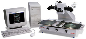
The Thales Optem Digital Transfer Scope
The Digital Transfer Scope (DTS) manufactured by Thales Optem (Rochester,
N.Y.) allows direct digital interpretation and compilation of features
from aerial photographs, in either monoscopic or stereoscopic view. This
new instrument combines the image-adjustment properties of the older Zoom
Transfer Scope, but in digital form. An advanced stereo microscope, designed
to function as a stereoscope, allows the viewing of photographic transparencies
or contact prints in either monoscopic or stereoscopic modes. Variable
magnification is available that is independent for each eyepiece. As a
result, photographs of different scales can be viewed in stereo. A built-in
computer monitor allows the simultaneous viewing of digital map data superimposed
over aerial photographs. A digital input for computer data and an output
port for attaching a digital camera are provided as an integral part of
the instrument. A film-scanning stage, similar to the viewing stage on
the Bausch and Lomb SIS 95 image-interpretation station, is set over variable-intensity
illuminators for use with photo positives of differing densities. The
scanning stage accommodates standard 9x9 aerial photos, although smaller
photos of any size can be used. Illuminators for contact prints are attached
to the sides of the instrument. As currently configured, this instrument
is fully self-contained and requires only an electrical power source and
a computer. Any computer that runs ESRI's ArcView(r) V.3.x can be used.
The software that enables direct digital transfer of photo-delineated
features is an extension of the ArcView software and is packaged with
the instrument.
Since the images - in this case analog
aerial photos - are in hard-copy form, the digital map data shown as an
ArcView shape file is adjusted to fit the current aerial photograph being
viewed. Map data can be rotated, scaled, stretched, zoomed or warped to
fit the same area that is shown on the photograph. When warping, GCPs
are selected and an affine transformation is applied to all shape files
that are loaded as themes in that particular DTS view. The process is
rapid, depending upon the speed of the computer processor and available
memory (RAM), and it may be re-run several times to get an acceptable
fit. Prior to applying the warp function, a report is produced that lists
the RMS errors of each point and the combined effect of all points. Using
this control point report, new points can be tested before the transformation
is applied. Point, line or polygon features can be compiled and edited
by using a mouse, a trackball, or a pen stylus. The compiling is done
while viewing the map data superimposed over the current image, either
in a point or a freehand (streaming) mode. Once the features have been
added, the map data can revert to its original coordinates along with
the newly compiled data. As a result, data that are added from the uncontrolled
photo will now be located in the controlled map space as a new theme.
Additional functions provide for image
registration and placement, switching of color selections from normal
to negative, the calculation of feature geometry (length, area, etc.),
and all the attribute and feature-editing capabilities of ArcView.
Comparison of Results
When comparing the use of the DTS to conventional methods for compiling
forest stands, roads, water, and other features associated with forest-type
mapping, using the DTS cuts processing time by 20 to 49 percent. An even
greater savings of time occurs when less-experienced GIS personnel use
the DTS. This is probably due to the reduction in the number of steps
necessary for complete mapping (production of a planimetric base, transfer,
edits, digitizing, etc.), in addition to increased speed in creating point,
line or polygon features. Training time varies depending upon the experience
of those using the DTS. On average, one's production ability climbs steadily
after a few days of practice. Regular use reduces familiarization lag
time, and operators who use the DTS from two to three days per week develop
a high level of proficiency for production work after only four to six
weeks. This time can be reduced even more if an experienced operator is
available onsite to coach new users.
A comparison of the DTS against systems
described in the section on Digital Image Methods is a limited one. However,
when reviewing all the steps that are necessary to get to the point of
delineating features in a digital mode, not having to scan and rectify
photos to view them in stereo on a monitor could produce a savings in
time of at least 25 percent, depending upon the software and computers
involved.
Conclusion
There appears to be a clear difference in the choice of methods to allow
digital compilation of data from images. If the images are digital to
begin with, then the use of an image processing system to rectify and
perform feature delineation may be the most advantageous. If the source
of image data is aerial photography (whether contact prints or transparencies),
the advantage seems to point toward the DTS instrument. With its excellent
optics, the DTS provides a straightforward approach that can be mastered
without extensive training in GIS or remote sensing. Users who are familiar
with the older technology of the Bausch and Lomb Zoom Transfer Scopes
(either mono or stereo) should find the functionality of the DTS reasonably
familiar, albeit in a digital context. Users experienced in ArcView should
adapt quickly to the DTS.
About the Author:
Roger H. Greene is president of Landmark Applied Technologies
(Bucksport, Maine). He may be reached via e-mail at: [email protected].
Back
|